Construction
The winter quarter covers the construction of RC parts and construction of the RC car itself for the RC Baja project. The student will be 3D printing most of the parts created, however, the shafts and steering rod will be machined, because they need to be stronger than 3D printed parts. After all the parts are made and gathered, the student will start constructing the RC car and sub-assemblies. The goal of winter quarter is to complete the construction and functioning RC Baja car.
Construction Video
Manufacturing Method
The student plans on using three different manufacturing methods to create the parts necessary for the RC Baja car. The first is 3D printing, the student plans to 3D print the motor mounts, differential box, and gearbox. The student decided to 3D print these parts, because they are more difficult and complex to create and would be hard to machine as a single part. The student decided to lathe the drive shafts for the drive train, this includes the axil, differential shafts, and gear box shafts. The student found it more beneficial to buy a single shaft and lathe the shaft to the correct sizes needed throughout the drive shaft. The last manufacturing method chosen would be laser printing or plasma cutting the steering rod. This is because the steering rod is a more complex part, but still needs to be durable and be able to handle stress and shock applied to the rod.
The student will be manufacturing parts in the middle section of the quarter from weeks 3-7. This will take place after the student purchases a majority of the parts needed to take the appropriate dimensions needed to begin manufacturing the part(s) associated with the measured dimensions. For example, the student waited until after receiving the motor and measuring the motor to finalize and 3D print the motor mount parts.
Drawing Tree
The drawing tree is a hierarchy style of organization that depicts which parts are associated with with sub-assemblies, which sub-assemblies are associated with which assembly, and that the assemblies are all associated with the RC Baja Project. The student decided to sort the parts in terms of how they would be physically assembled when it came time to assembling the RC Baja car. So, this went from motor, to gearbox, to differential, to axil down the drivetrain then the steering that will be separate from the drivetrain. This way, what ever parts needed to be assembled first took precident over which assembly they would typically be associated with, for example the bevel that connects to the differential is not in the differential assembly, because it would have to be taken off in order to assemble the differential box which is part of the drivetrain sub-assembly that includes the axil. Finally, another level of organization the student added was color association. Each color has a different meaning, red are parts that were ordered (50-###), green are machined/3D printed parts (20-###), light blue are sub-assemblies (10-###), purple is student designated assembly, and navy is the total project assembly. This way the student and anyone giving the drawing tree a quick glance can more easily recognize a parts significance and association with other parts of similarity. The student designated assemblies are how the work was divided in RC Baja, steering and drivetrain being one half and chassis and suspension being the other half of the overall RC Baja project.

Baja Assembly
The assembly includes all the parts that the team has designed to complete the RC Baja project. The team decided to omit some of the purchased parts for the time being, as most of the purchased parts did not come with part files. So, this will instead be used as a rough layout to aid in the construction of the Baja car when the students begin the assembly, which will be completed when the students know the correct dimensions of the parts missing.

Motor Assembly
The motor assembly (PAR-10-001) includes four different parts, by name they are PAR-20-002, PAR-20-003, PAR-20-012, and PAR-55-005 (parts list link). This is the motor with two flat motor mounts, a top motor mount, and a front motor mount. The front motor mount was designed to incorporate the screw pattern on the motor and to translate torque from the motor to the drivetrain. The screw holes that mount to the chassis are the size of common VEX screws, as the student has easy access to those screws. This assembly could not be completed, however, because the student did not incorporate the motor shaft hole in the original design, so the student plans on drilling a hole that will fit the motor shaft to complete the assembly.

Differential Assembly
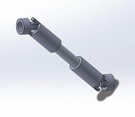
The image on the left is of the CAD Assembly for the Differential (PAR-10-003). The parts included in this assembly are PAR-50-009 and PAR-20-007, which are two differential yokes with the differential shaft combining the two yokes. The shaft was lathed then filed down to aproximately .2in diameter to fit into the yoke and is allowed to adjust when compressed through the use of a sliding pin support. This assembly will be used to combine both the gearbox and differential box in the full assembly.
Divetrain Assembly
This image shows the CAD file of the Axil (PAR-10-004). The parts included in this assembly are PAR-20-004, PAR-20-005, PAR-20-008, PAR-55-007, PAR-55-008, and PAR-55-010, which are both differential box top and bottom, the axil, both bevels, and two tires. The axil was very difficult to machine due to its long length of 12in and small diameter of .235in, so the student had to lathe the shaft in four sections and even still had to file most of it to get it to a some what uniform diameter. The wheels were drill pressed to fit the diameter of the axil and the bevels are located in the differential box. The student redesigned had to go through two redesigns of the differential box to get the correct shape and functionality for the differential to transmit torque to the axil, this design is the first iteration of the differential box.


Steering Servo Assembly
This image depicts the CAD assembly for the Steering Servo (PAR-10-005). The parts included in this assembly are PAR-20-006, PAR-55-011, and PAR-55-012; which are the servo mount, steering servo, and servo horn respectively. The current design decision is different than the one depicted in the Baja assembly picture above, as this design has the servo laying on its side, where as in the picture above, it is standing upright. This decision was made to more easily mount the servo to the chassis and a more streamline transmission of torque to the tire spindles. The horn in the current picture is not the servo horn in the final design, the new horn has two screw holes side by side at the top to allow for easier and smoother steering of the Baja Car.